Temperature Logger for 10" Newtonian telescope

This is a quick description of a 4-port temperature logging unit I built about a year ago to monitor the mirror and ambient temperatures on my newtonian telescope. You can read more about this unit and see some pretty graphs here

The parts used in this unit are:

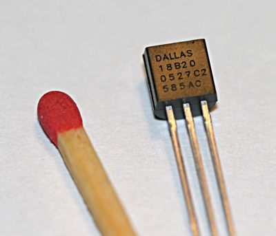
The DS18B20 digital Temperature sensors, in a to-92 case.
The datasheet is here: DS18B20.PDF (Acrobat Reader required).

This sensor can be operated in a number of different modes, including connecting several sensors together on the one common line. For the temperature logger I use the simplest arrangement, with each sensor on a separate line, and providing power to each sensor.
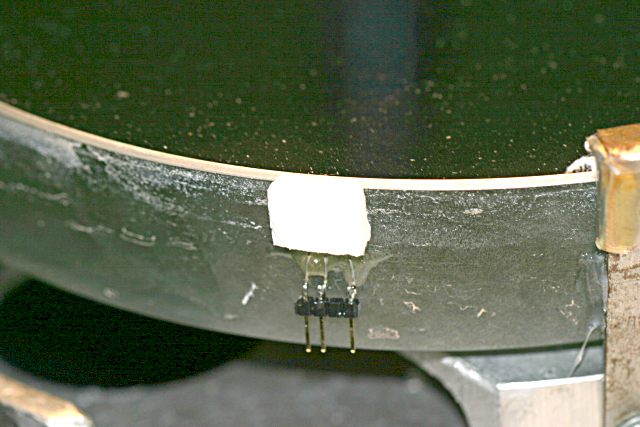
Here we see one of these sensors attached the the side of my primary mirror, as close to the top (reflective) surface as I was game to put it. The sensor is placed so that it's flat side is against the glass and I used a tiny drop of thermal conductive paste between the sensor and the glass to make sure I had the best contact.

My, that mirror looks grubby. Must be time for another clean...

The sensor is then covered completely with an insulating cap made from styrofoam. The styrofoam is held to the glass with a small amount of araldite (epoxy resin). I was concerned about possible stress on the mirror from this so I used only the smallest amount that I could.

The sensor is mounted onto a 4-pin wide strip of header which has one of the middle pins removed so that I can easily attach a connector and there is no doubt which way is the right way. In the matching plug I filled the unused hole with epoxy resin so that the plug will not go on the wrong way.
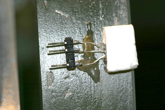
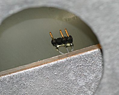
A closeup of the previous sensor, showing more clearly how it's stuck onto the mirror.
Looking at the back of my mirror through the mirror cell, this is the second sensor that is attached to the back of the mirror. All we can see here is the connector, the actual sensor is hidden behind the aluminium mirror cell.
You can buy strips of pins on plastic headers like this from Jaycar or Dick Smith.
Here's one of the connectors that plugs onto the temp sensor. Note that it has one of the middle holes empty to match with the pins on the sensor.

You can just about make out that the empty hole is filled with epoxy resin to block it up and prevent the plug going on the wrong way around.
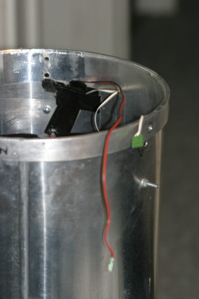
Here is a shot that shows the two connectors and the 3-wire cables that runs back into the tube and to a pair of 3.5mm sockets. These connectors allow the mirror to be unplugged when I remove it from the tube.

The primary mirror and cell are not in the tube (obviously). You can see the mounting holes for the mirror cell near the end of the tube.
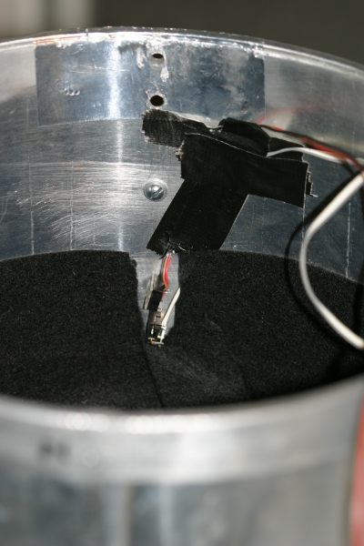
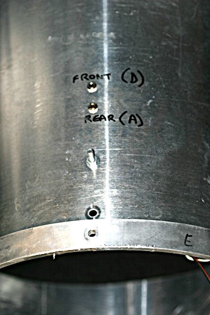
A closeup of the 3-wire cables running into the mirror end of the tube to a pair of 3.5mm stereo sockets.
A closeup of the outside of that part of the tube showing the 3.5mm stereo sockets. When the mirror is fitted to the tube these sockets provide the connection between the temp sensors on the mirror and my temp logger box.
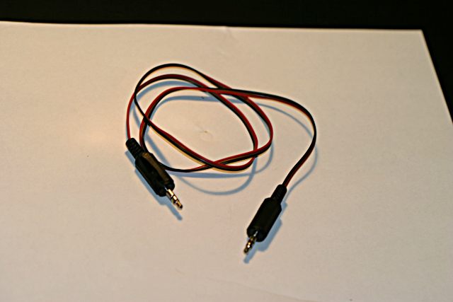
The cables that I use to connect the 3.5mm sockets on the tube to the 3.5mm sockets on the temp logger. These are straight-through 3 wire cables.
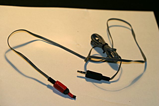
This is a temp sensor on it's own cable that I use for measuring tube temperature. I clamp the temperature sensor under one of my tube straps when the tube it on the mount and plug the cable into the temp logger. The tube strap "hides" the sensor from the outside air so that it is reasonably insulated.

I used an empty 3.5mm backshell to support the sensor, and filled it with expoxy resin to hold it in place.
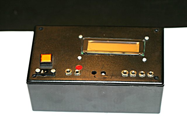
Here's the rough-and-ready prototype for the temperature logger unit. The 4 sockets on the right are for temperature sensors, and the socket on the left with the red dot is the serial data out to the host PC.

The other socket on the left is connected to the programming socket on the PicAxe microcontroller and I use that to upload the program to the microcontroller when I change it.
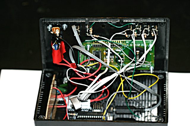
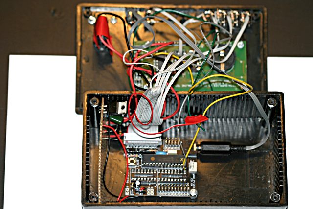
Uh Oh, I'm not sure we should be opening this...
Oh dear, what a mess.

You can see the inside of the 4 temperature logger sockets at the top, with the ribbon cable bringing the signal for each sensor back to one of the I/O sockets on the microcontroller board.

The small board that's mounted vertically on the left is a 5v voltage regulator that is used to supply power to the LCD display (shown at the top). This way I can supply 12v to the box instead of having to supply separate 12v and 5v rails.

The yellow wire is the serial line connection from the microcontroller board (bottom) to the LCD display board (top). When I want to make stuff appear on this LCD I write data to that line (line 7).

The less said about the construction of this box the better...

Software

The microcontroller is programmed in a version of BASIC that is then cross-compiled on a Windows PC to assembly code and uploaded to the microcontroller via a dedicated serial port.

You can see a commented version of the code for my program here: Temperature Logger Software.

Anthony Wesley
9th November 2005